insulation diagram
Insulation at the vertical slab edge and under the will vary by location. The insulation diagram is is very helpful tool for the manufacturer and the tester to identifiy where such MOP are implemented in the device and which requirements apply to.

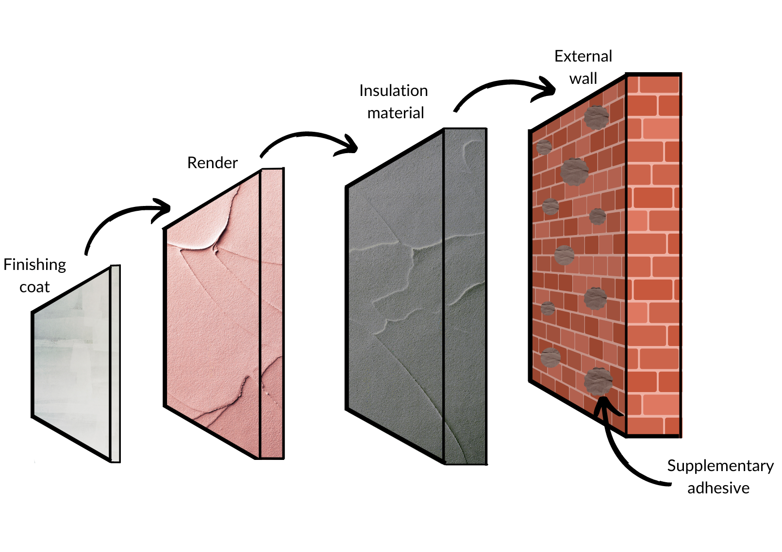
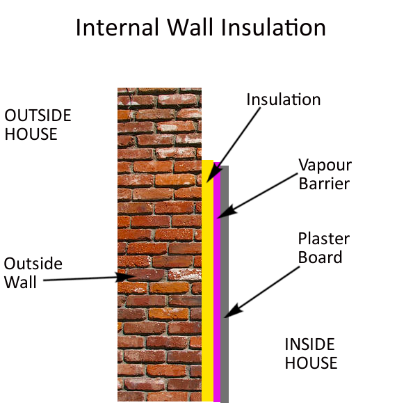
External Wall Insulation Download Scientific Diagram
This instrument can be power-driven through an inbuilt DC.
. The illustration above shows all the areas of the home where there should be insulation. The most common one is tube form where the copper or drain pipe is slotted into the tube insulation by hand. Insulation diagram is a graphical representation of equipment insulation barriers protective impedance and protective earthing.
MOOP MOPP CTI unless is known Working voltage Required creepage mm Required clearance. Slab perimeter provides this bond break. The diagram to the right shows and example of a slab on grade that is structurally.
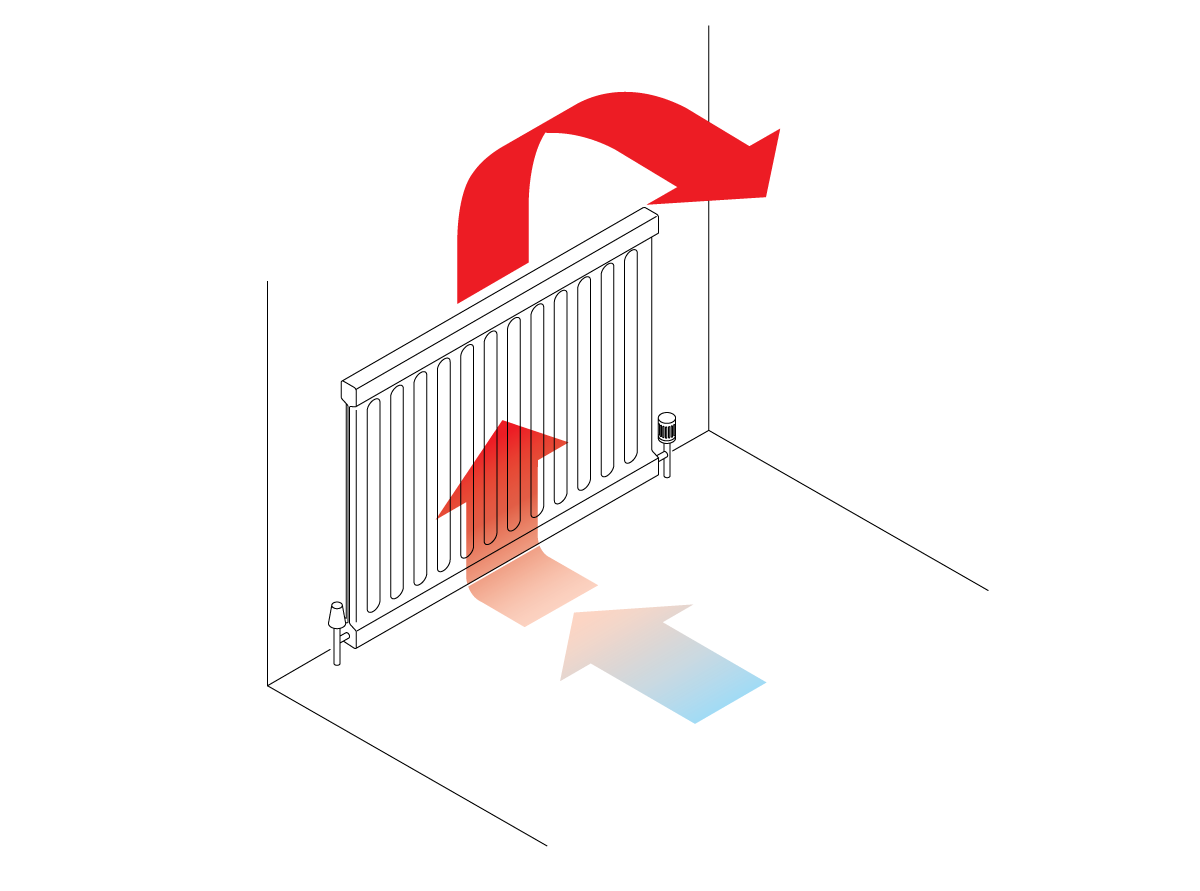
Diagram of a room ventilated by ceiling built-in air ventilation and and cooled by wall fan coil unit Energy efficient house concept with classification graph stock. An isolation diagram is a GREAT tool to communicate spacings and dielectric requirements of the standards to the designers of the product. You may also be able to identify.
Hands putting insulation on. Pennsylvania Housing Research Center. In unfinished attic spaces insulate.
The tube insulation has standardized sizes in accordance with the size of. If the reading is reduced to a megger value then the windings have to be checked and. If feasible use the following conventions to generate the.
The numbered areas shown in the illustration are as follows. House with additional insulation and energy saving technologies. This is an excerpt from the course Introduction to Safety for Electrical Medical Devices and IEC 60601 which is available at.
Diagram of a detached house with additional wall and roof insulation and sketches of modernenergy saving technologies. The readings are logged down the graph is plotted and the trend of insulation resistance is checked. Insulation Resistance Test Circuit Diagram Insulation resistance can be measured by using an instrument namely a megger.
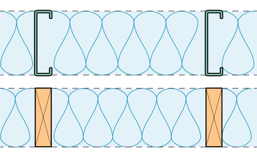
Test Measurement Instruments with Engineering Support Instrumart. INSULATION DIAGRAM example Area IIIb Number and type of Means of Protection.
Effective Insulation R Values In Steel Vs Wood Framing 2017 05 29 Building Enclosure

Measurement Of Insulation Resistance Electrical4u
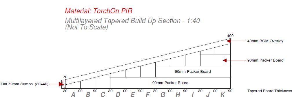
Sig Design Technology Tapered Insulation Diagram Sig Design Technology
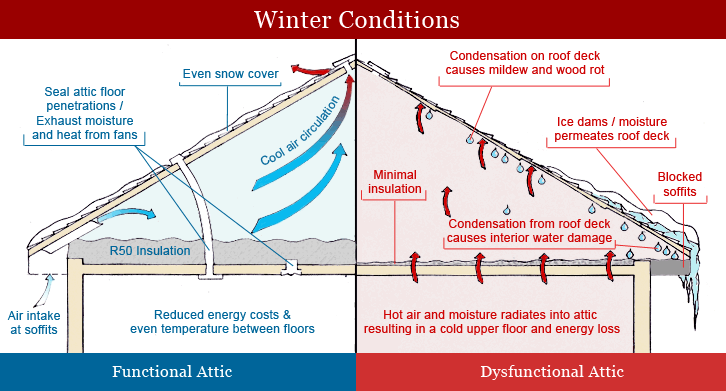
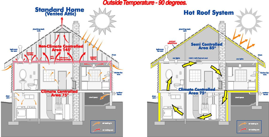
Attic Insulation Diagram Positives Ventilation
Can Wall Insulation Reduce My Energy Bills Rms Energy Solutions

Insulation Frontiermetal
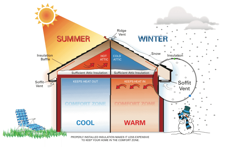
How Does Insulation Work The Renewable Energy Hub

Energy Efficient Insulated House Illustration Stock Image C050 7533 Science Photo Library

Aluminum Neo Roof Thermal Insulation Materials Thickness 4 15 Mm At Rs 85 Square Meter In Jaipur
The Science Of Insulation Explained Knauf Insulation Australia

How We Insulate Our Garden Buildings

Electrical Medical Devices Developing An Insulation Diagram

How To Insulate An Attic Hometips
Energypro Insulation

Specifications Insulation Diagram Roof Crushed Stone Insulated
Building Guidelines Internal Wall Insulation Diagram Flat Roof Parapet
Home Insulation Contractors Michigan Pro Home Improvement